KFRDRY01 -- Retrofit Motor for Oblique Seat Valves (Wired Control)
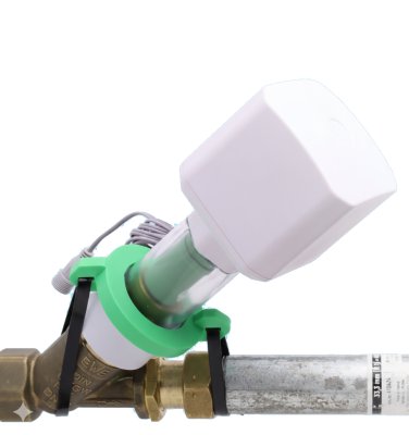
Product Description
The motor drive for oblique seat valves (KFR valves) enables retrofitting of existing and already installed shut-off valves into remotely controllable intelligent devices, without interrupting the water supply or cutting into the water pipe.
The motor is powered by a 12 V power supply and is fully water and dust protected (IP67) up to the power supply. Optionally, a battery pack is available for mains-independent power supply.
Various adapter rings and a sophisticated coupling system allow the motor to be used on all modern oblique seat valves from DN15 to DN32. Thanks to an additional water sensor that plugs directly into the device, the motor can be used for leak protection without any wireless connection whatsoever.
Control: Via a 120 cm two-wire cable (dry contact).
- Closed switch -- Valve closes
- Open switch -- Valve opens
Compatible with smart home systems: Shelly, Z-Wave, SmartThings, Bosch, Homematic, and alarm systems.
The control cable can be extended with a 1.5 m extension ALIEXT01 (available in the shop).
If no switching contact can be installed near the valve, the two-wire cable can be extended wirelessly. See KFRDRY02.
Motor Drive Components
| Abbr. | Component | Image |
|---|---|---|
| H | Handwheel | 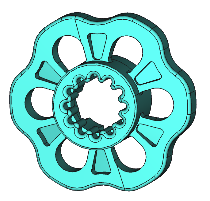 |
| K | Inner coupler | 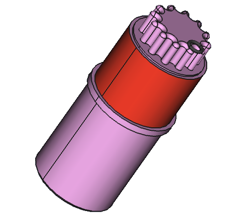 |
| Ax | Adapter rings (A1--A4) | 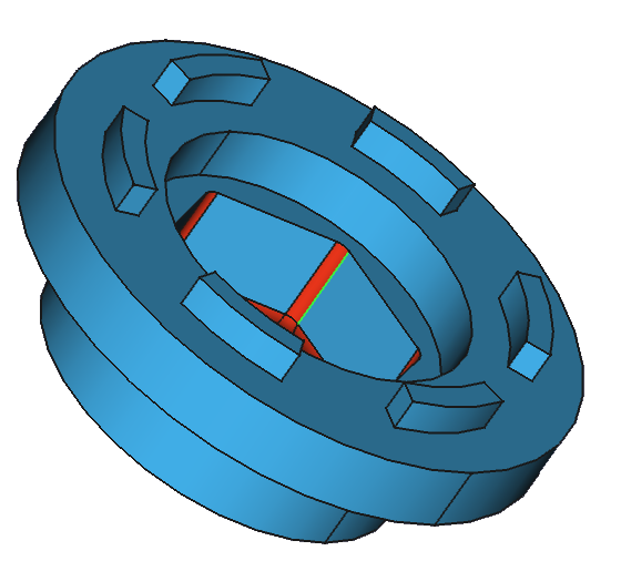 |
| D1, D2 | Spacer rings (12 mm, 24 mm) | 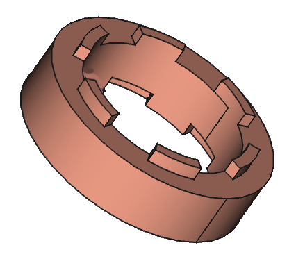 |
| Ws | Ball bearing seat | 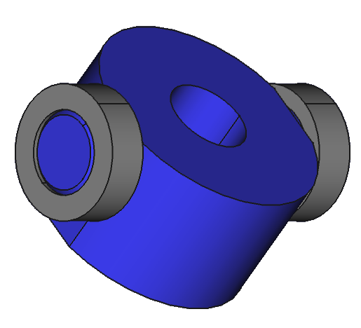 |
| M | Motor with button | 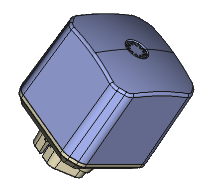 |
| G | Enclosure | 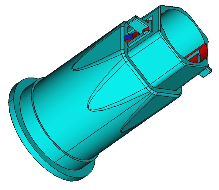 |
| N | Retaining bracket | 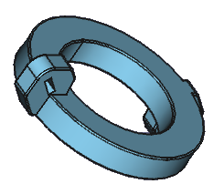 |
Motor Drive Assembly
Mounting on the Shut-Off Valve
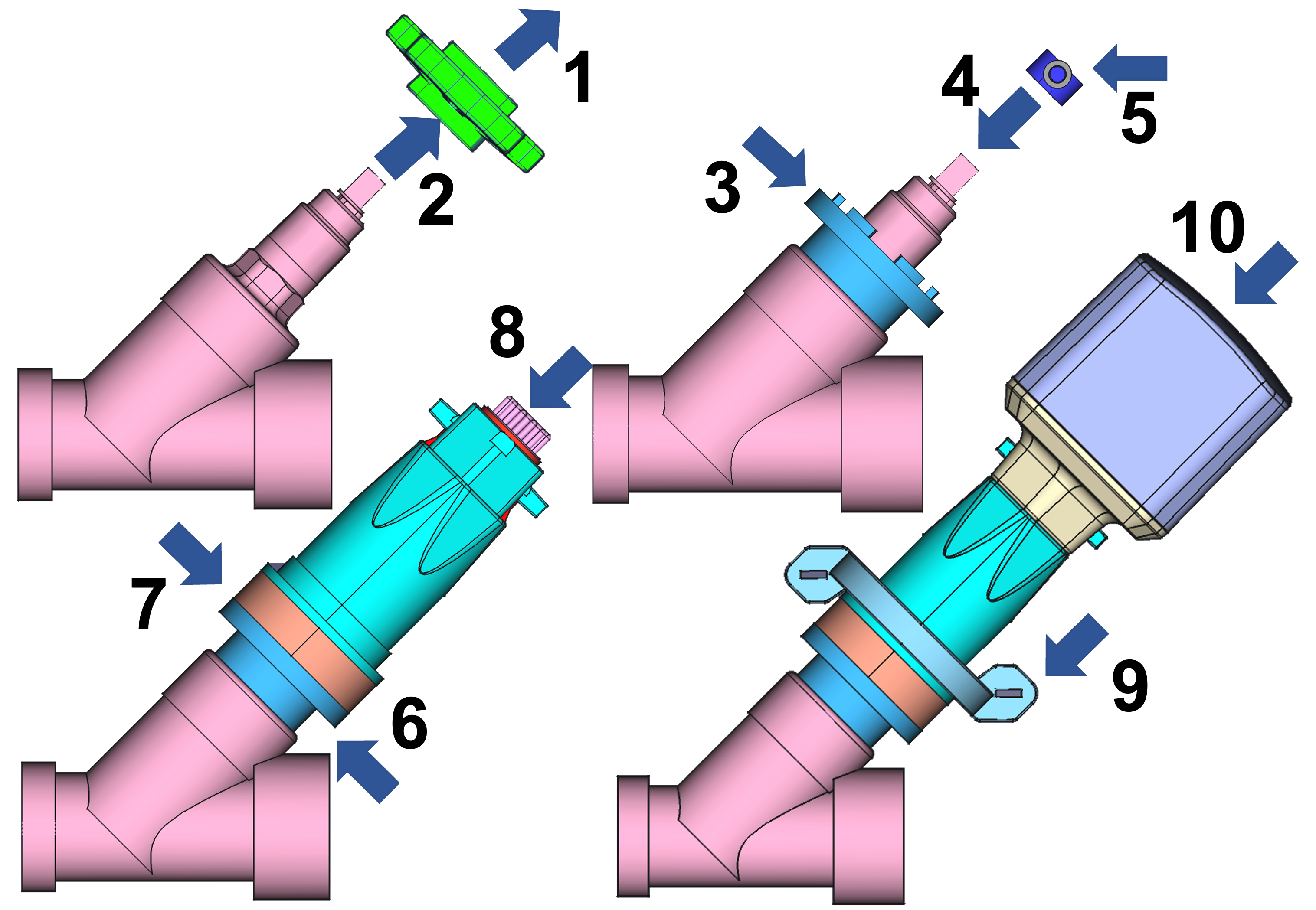
- Loosen the screw in the center of the handwheel
- Remove the handwheel
- Select adapter A1--A4 (M17, M22, M27, M30)
- Place ball bearing seat W1--W3 onto the spindle (6x6, 7x7, 8x8 mm)
- Secure the ball bearing seat with a screw
- Add spacer rings D1/D2 if needed (12 or 24 mm, combinable to 26 mm)
- Place the enclosure
- Insert the inner coupler (transparent enclosure allows visual verification)
- Secure the retaining bracket around the pipe with cable ties
- Place the motor head onto the enclosure
When placing the motor head, ensure that the gears mesh correctly. If there is resistance, rotate the motor slightly.
Wilhelm Ewe GmbH Valves
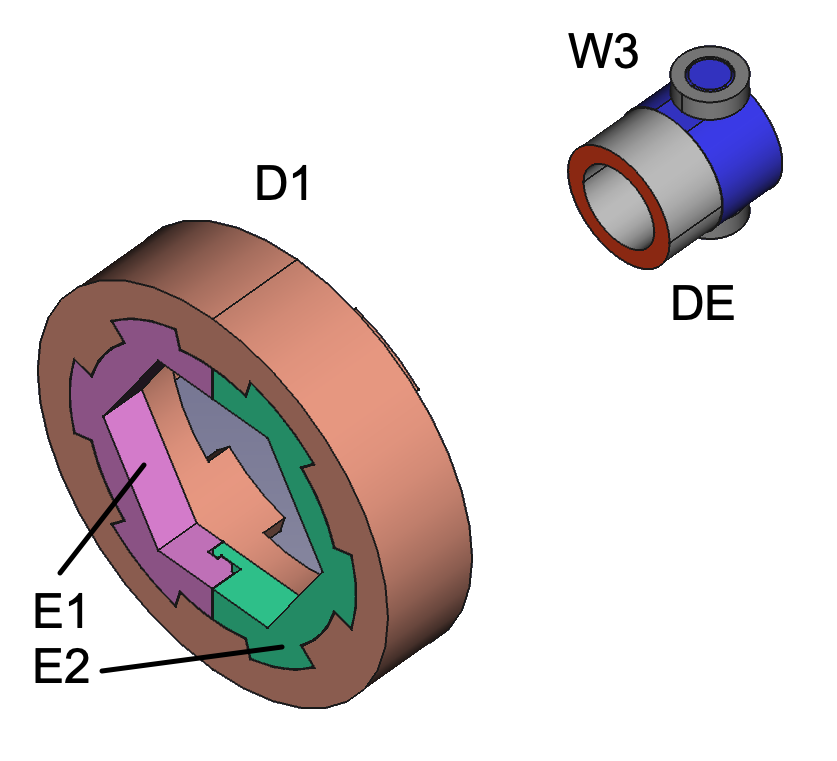
Insert the split ring (E1+E2) into the 24 mm spacer ring instead of an adapter. Place the small spacer ring (DE) under the ball bearing seat for the grease chamber.
Setting the End Positions (Calibration)
The new calibration requires that the motor is installed on a valve and remains there after calibration. This also means recalibration no longer happens on every new power-on.
In the factory state, calibration mode is already active; otherwise it must be activated with a triple click. Active calibration mode is indicated by rapid LED color changes Red -- Yellow -- Green.
Calibration procedure:
- Before calibration, the valve should be manually closed just enough so that no more water flows, but not necessarily further.
- Then place the motor head on top.
- Pressing and holding the button now moves the motor towards the OPEN position. Once the OPEN position is reached, release the button.
- A triple click on the button saves exactly this value as the OPEN position.
Fine tuning:
- Double click: reverses the motor direction again -- that is, you can then drive the motor back towards the CLOSE position.
- Short clicks: advance the motor only a very small step each time, specifically 1.25 revolutions. This makes it possible to move the motor a small amount in the CLOSE position as well, in case it was not possible to place the motor head exactly on the coupler in the CLOSE position.
- Triple click: the maximum positions reached for OPEN and CLOSE are then stored as the end positions.
Once the end positions are stored, the motor no longer drives hard against the end points but counts the revolutions and approaches the end points gently.
Enabling/disabling seal relief:
If the rubber seal has become brittle from prolonged closing or aging, the slight back-turn may lead to a leak. This function can therefore be disabled:
- Via the button: Hold for 6 seconds (6x buzzer), then release
- 2x beep + 2x green LED = active (factory setting)
- 3x beep + 3x green LED = disabled
On-Device Operation
The device has a single button with a built-in tri-color LED. To toggle the valve, you can click the button or hold it for several seconds. The motor beeps every second as a counting aid.
The device is designed for outdoor use and prevents malfunctions caused by water droplets on the button. Therefore, please press the contactless button firmly, even for a short click.
Button Operation
| Action | Function |
|---|---|
| 1x click | Toggle motor (open / close) |
| Hold 2 sec | Deactivate alarm |
| 2x click | Send status report |
| 3 sec + 1 click | Enable button lock |
| 3 sec + 3 clicks | Disable button lock |
| 4 sec + 1 click | Motor stays closed after sensor alarm (factory setting) |
| 4 sec + 2 clicks | Motor reopens immediately after sensor alarm |
| 6x click | Seal relief on/off (2x beep + green = active, 3x beep + green = disabled) |
| 10 sec + 5 clicks | Full motor reset (3x beep + 3x red LED = OK) |
LED Signals
| LED | Meaning |
|---|---|
| Green slow flashing | Valve open |
| Red slow flashing | Valve closed |
| Red+green fast flashing | Motor is moving |
| Red flashing | Alarm |
| Red triple flashing | Motor is blocked |
| Yellow flashing | Searching for radio network connection |
Package Contents
- Motor with power cable (150 cm)
- 4x adapter rings (M17, M22, M27, M30)
- 3x ball bearing seats (6, 7, 8 mm)
- Spacer ring + split ring for Ewe valves
- Bracket + 2 cable ties
- Main enclosure + internal coupler
- 2x spacer rings (12 mm, 24 mm)
- Connection cable for switching contact (120 cm two-wire cable)
- Power supply (150 cm)
- Replacement handwheel
- 57 g epoxy resin
- User manual
Technical Specifications
Motor Drive
| Parameter | Value |
|---|---|
| SKU | KFRDRY01 |
| Speed | 15 rpm, max. 40 s open/close |
| Power | 10.95 W |
| Gearbox | 1:704, max. 4.5 Nm |
| Noise | <50 dB |
| Adapters | M17, M22, M27, M30 |
| Valve spindle | 58--135 mm |
| Pipe diameter | DN15--DN32 |
| Weight | 380--420 g |
| Dimensions | 70 x 170--195 mm |
| Motor | ~400 mA, standby ~50 mA (12V) |
| Protection rating | IP67 (power supply IP20) |
| Operation | -20 to +60 °C |
| Storage | -30 to +70 °C |
| Minimum wall clearance | 35 mm |
| Vertical clearance required | 175 mm above pipe diameter |
| Vibration | <10 dB |
Communication
| Parameter | Value |
|---|---|
| Control | Two-wire (dry contact), 120 cm |
| Radio | No radio module |