AQMLWU01 – Aqua-Meter Ultrasonic Clamp (LoRaWAN-US)
Product Description
The water sensor clamp uses a "Time of Flight" measurement method to measure the flow rate and temperature in a water pipe and transmits the data wirelessly. Through internal flow analysis, water leaks and other anomalies are detected and the owner is alerted.
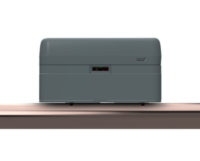
The device is clamped onto the water pipe from the outside without interrupting the water supply. The flexible design and innovative software enable use on water pipes between 16 and 50 mm with many currently available materials such as PEX, PEX AL, soft plastic-coated soft copper, or PE. All requirements of the European Community's Measuring Instruments Directive (MID) are met. With only 60 mm of clearance above the water pipe and a length of 115 mm, the device is very flat and short, making it easy to install.
The device can be powered either via USB-C or two AA alkaline cells. Whenever an external power source is available, it is used regardless of any installed batteries.
The device is controlled via LoRaWAN commands and operates as a LoRaWAN Class A device (US915 frequency band). Using the device requires LoRaWAN network coverage. Otherwise, you must install and operate your own LoRaWAN gateway.
This device is the US variant of the AQMLWE01 and operates on the US915 frequency band instead of EU868. Hardware and functionality are otherwise identical.
Measurement Principle
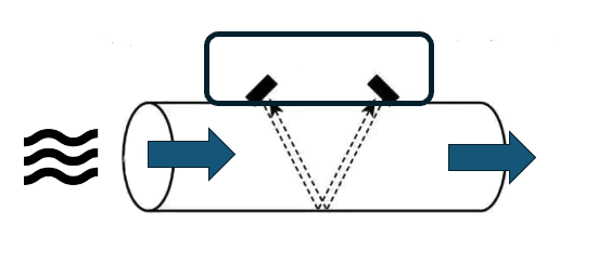
The water sensor clamp uses ultrasonic waves and the "Differential Time of Flight (DTOF)" method to measure water flow. In this method, two ultrasonic transducers are used to send signals in opposite directions through the pipe and water. The signal sent by the upstream transducer travels along the water flow direction and is detected by the downstream transducer. The second signal, sent by the downstream transducer, travels against the water flow direction, moves more slowly, and arrives later at the upstream transducer. The difference in transit time between the two signals is directly proportional to the velocity of the water in the pipe and thus to the flow rate.
To better understand this method, imagine swimming in a river current. By swimming upstream and downstream and comparing the time needed to cover the same distance in each direction, you can estimate the speed of the water flow in the river.
The device's test signal has a frequency of 1 MHz and is of very low power, making it inaudible and harmless to humans and animals. Furthermore, the sound waves at this high frequency are strongly attenuated by the atmospheric pressure of the air and cannot practically radiate beyond the pipe. The water sensor clamp will therefore not disturb people or other devices.
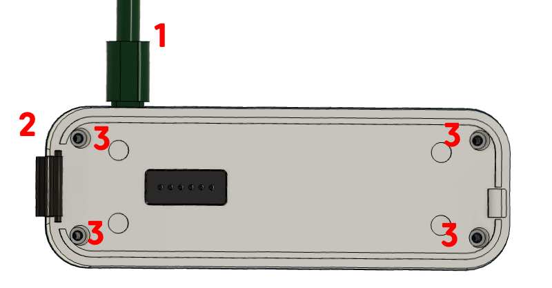
Sensor Construction
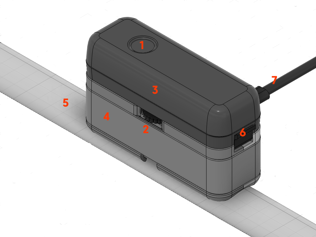
The sensor consists of two main components:
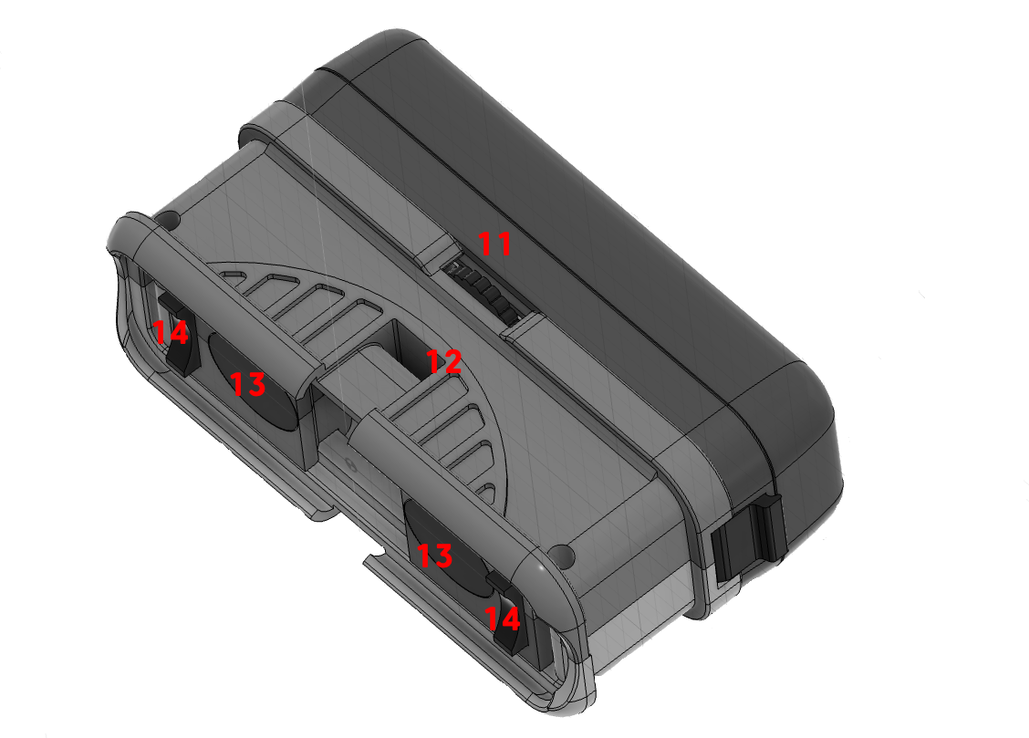
- Sensor Base (4): Connects to the water pipe. It contains the temperature sensor and two ultrasonic transducers (13). Their spacing can be adjusted using the thumbwheel (2/11) to match the pipe diameter (5) and material of the water pipe.
- Electronics Capsule (3): Contains electronics, batteries, LED (1), button (1), etc. It is placed on the sensor base and secured with a latch (6). As an alternative to batteries, the sensor can be powered via a USB-C power supply (7).
Two small spacer adapters (14) are required to fix the base to the pipe, which must match the exact diameter of the water pipe. A selection for common pipe diameters is included with the product. Additionally, the sensor must be firmly mounted to the water pipe using a cable tie or alternatively a hose clamp.
During operation, the capsule is firmly connected to the base. For maintenance or battery replacement, it can be safely separated from the base. If the capsule is powered without the base, a corresponding alarm message is triggered and no water consumption measurement is possible.
Installation
The mounting location and correct attachment of the sensor to the pipe have a decisive influence on measurement accuracy. An unfavorable mounting location or incorrect attachment of the sensor can, in extreme cases, result in the sensor delivering no measurement results at all.
Finding a Suitable Mounting Location
(1) For accurate measurement, the water must be free of turbulence and air bubbles. Therefore, the device must not be installed near pipe bends or other water installations such as main shut-off valves, backflow preventers, or pressure reducers. A minimum distance of 20 cm must be maintained on each side of pipe bends, etc., and the installation point must not allow the accumulation of small air bubbles that occur whenever water flows quickly through the pipe.
(2) The pipe at the mounting location must be smooth and rust-free so that no air pockets on the outside interfere with the measurement process. For plastic pipes, cleaning the surface is sufficient; for metal pipes, it may be advisable to polish them with fine sandpaper.
(3) Last but not least, the mounting location must be reachable by radio. A stable radio connection is most easily tested by connecting the sensor to the radio network before final installation.
- Clean, rust-free pipe
- Min. 20 cm distance from bends and fittings
- Not on descending pipes
- Radio network coverage (LoRaWAN US915)
Preparing the Sensor for Installation
It is recommended to connect the sensor to the radio network at the installation site but before final mounting on the water pipe. However, this is not an installation requirement.
- From the set of spacer pieces, select the two parts matching the pipe diameter and insert them into the corresponding slots next to the transducers.
- The transducers on the sensor base can be moved using the small thumbwheel on the side and can thus be adjusted for different pipe diameters and pipe materials. The transducers can be spread up to 26 mm apart. Table 1 provides the necessary distance in millimeters for various pipe diameters and materials. If the pipe is jacketed (e.g., PEX with aluminum jacket or copper with plastic jacket), select the base material from the table. The distance should be set with an accuracy of +/- 2 mm.
| Diameter | 20 mm | 26 mm | 33 mm | 42 mm | 56 mm |
|---|---|---|---|---|---|
| Soft Copper | 0 mm | 0 mm | 5 mm | 13 mm | 20 mm |
| PEX | 0 mm | 0 mm | 5 mm | 20 mm | 20 cm |
| PP | 0 mm | 0 mm | 5 mm | 15 mm | 18 mm |
Table 1: Transducer distances depending on the water pipe used
- The contact pads are adhered to the transducers. First, peel off the white protective film and place the adhesive pad directly over the transducer surface. The adhesive pad should be flush with the side of the housing facing the other transducer. Remove the red protective films on the transducer contact pads. The buffer pads are very sticky and will hold the sensor to the pipe without additional fixation. Initially, press the pads only very lightly so they can be removed again if needed. If you damage one or both pads during removal, replacement pads are included with the product.
- Observing the flow direction (large arrow on the device's nameplate), place the sensor against the water pipe and loosely secure it with the cable tie.
- Set the transducer distance
- Do not press the contact pads too firmly
- Observe the water flow direction
Mounting the Sensor on the Pipe
The precise positioning of the sensor on the pipe has a decisive influence on the device's functionality and accuracy. The following must be observed:
- The sensor must be placed absolutely parallel to the pipe. The spacer pieces help achieve exactly this goal.
- The sensor should be mounted on the side of the pipe. Air bubbles can collect at the top of the pipe, and deposits can accumulate at the bottom.
- The sensor must have a defined distance from the pipe, which is completely filled by the contact buffers. The spacer pieces also help achieve exactly this goal.
- The contact pressure of the sensor must be optimal. This needs to be optimized during installation itself. A positioning aid is available for this purpose if needed.
Secure the sensor with the included cable tie. The cable tie must be tightened as firmly as possible. Then power the sensor. Once it has connected to the radio network, the LED will blink either slowly red or slowly green:
- Slowly green (every 5 seconds): Device is ready for operation.
- Slowly red: Positioning needs to be optimized.
Always mount the sensor on the side of the pipe, not on top or bottom. This improves measurement accuracy and prevents deposits on the transducers.
Positioning Aid
The sensor has a built-in positioning aid that helps you:
- find the optimal position on the pipe
- set the optimal contact pressure of the sensor
- find the optimal transducer spacing
- correct tilted or twisted sensor placement
The positioning aid is started with three clicks on the button and works like a parking sensor in a car. The LED blinks red-yellow with varying proportions of red and yellow, later red and green. Additionally, the sensor beeps slower or faster.
The rule is: The more green and the faster the beeping, the better. No green means no working position.
You must now try to find a working position by changing the contact pressure or, if necessary, adjusting the transducer distance or the sensor position. As soon as the LED shows at least some green, you can end the process with a short click on the button. A post-calibration of approximately 30 seconds follows. During this time, the sensor blinks yellow. If no acceptable position is achieved, the sensor returns to the red blinking mode. Measurement of water consumption is not yet possible. You can repeat the positioning at any time or use it during operation by pressing the button for three seconds to check the optimal sensor fit.
Why does the positioning aid fail?
- No water in the pipe or too many air bubbles in the pipe: Find a position farther away from bends or downward-leading pipes.
- No water pressure in the pipe.
- Contaminated pipe surface: Please remove rust using the included sandpaper, possibly degrease the pipe or use the included ultrasonic gel for better connection between sensor and pipe.
- Insufficient contact pressure of the sensor on the pipe. This can lead to malfunctions particularly with metal pipes (copper or iron). Consider using a pipe clamp instead of the more convenient cable tie.
Calibration
Immediately after positioning, a basic calibration of the system is performed. The LED on the device blinks yellow for approximately one minute. During this time:
- the device must be mounted on the pipe,
- there must be water in the pipe,
- no water must be flowing.
After successful calibration, in mains-powered operation the green LED will briefly light up every 5 seconds, and in battery operation the LED will be completely off.
Ensure that no water is flowing during the calibration phase. Any water usage during this time will lead to inaccurate measurements.
Device Operation
Operating States
The sensor can be in various operating states, depending on its network connection status, the calibration of the measurement system, or a detected alarm. Each state is indicated by a specific LED blinking sequence.
(1) Red/yellow/green alternating every 200 ms (fast): The sensor is booting after power-on or reset and is searching for a network connection.
(2) Red/green alternating every second (slow): The sensor does not yet have a configured network connection and is waiting for network connection setup.
(3) Red/green every 100 ms (fast): The sensor is in WPS mode for quick connection to a Wi-Fi network (if available).
If none of these three LED combinations is visible, the sensor is connected to the network. It is then either in normal operating mode, alarm mode, or not yet calibrated. It is therefore not possible to calibrate the sensor on the water pipe until a network connection has been established.
(4) Red blinking every second (slow): The sensor has not yet been successfully calibrated. It will therefore only transmit temperature values but no consumption data. It must be calibrated. No alarms are activated in this state.
(5) Red-green alternating with varying green and red phase durations: Feedback during system calibration and positioning.
(6) Yellow every second (slow): Calibration after positioning.
After successful calibration and with an existing network connection, two possible operating states result. If the sensor has not yet been calibrated but is successfully mounted on a water pipe and receives a clean test signal, the calibration phase is skipped and the sensor automatically enters normal operating mode.
(7) Green flash every 5 seconds: The sensor is calibrated and operating normally. Temperature and consumption values are regularly transmitted along with all alarms. When water is flowing, the green LED blinks faster.
(8) Red flash every 5 seconds: The sensor is calibrated and operating normally, but an alarm is active. The reason for the alarm is transmitted via the network. If the reason for an alarm disappears, the alarm is cleared. An alarm can also be cleared via the local button, even if the alarm reason has not disappeared. The corresponding alarm reason then remains deactivated until the next boot (power-on or reboot).
| # | State | Start | End |
|---|---|---|---|
| 1 | Boot | After power-on or reset | Automatically to (2) or (4) or (7), depending on network availability and/or calibration |
| 2 | Network Search | Automatically from (1) | Successful network connection |
| 3 | WPS | During (2) single click | Single click, back to (2) |
| 4 | Uncalibrated | Network successfully connected | Triple click to (5) |
| 5 | Positioning | Triple click in (4) | Single click to (6) |
| 6 | Calibration | Single click in (5) | Ends automatically after 30 seconds |
| 7 | Normal | End of (6) or (1) or (2) | Alarm |
| 8 | Alarm | Alarm | Double click clears alarm |
LED Signals
| LED Signal | Meaning |
|---|---|
| Red short | Alarm active |
| Red long | Normal but not calibrated |
| Yellow long | Calibration |
| Green short | Normal |
| Green fast | Water is flowing |
| Red/Green fast | WPS active |
| Red/Green slow | Searching for network |
| Red/Green variable with beep | Positioning |
| Red/Yellow/Green | Booting |
Button Controls
| Action | Function |
|---|---|
| Single click | During positioning: stop positioning. During normal operation: send status message to network |
| Double click | Clear alarm |
| Triple click | Start positioning plus calibration |
| 3-second button press | Start positioning without calibration |
| 10x click | Reset to factory defaults |
Beeper
| Signal | Meaning |
|---|---|
| Triple short beep | OK |
| Approx. 3 seconds long | Error |
| Variable length | Sensor positioning |
Power Supply and Battery Operation
The device can be powered either via a USB-C power supply or two standard AA batteries. In the factory state, no batteries are installed.
To use the device with batteries, the battery compartment must be opened:
- Disconnect the device from the power supply.
- Separate the electronics capsule from the sensor base.
- Loosen all four screws and remove the cover from the electronics capsule.
After inserting two AA batteries (1.5 V Alkaline), replace the cover and secure it with the four screws. Whenever an external power source is available, it is used regardless of any installed batteries. The batteries then serve as a backup in case of power supply interruption.
In battery operation, power consumption must be reduced to a minimum:
- In normal operation, the LED is turned off.
- In alarm mode, the LED and buzzer are only briefly active at longer intervals.
- Individual water consumption events are not reported.
- Total consumption is only transmitted every hour.
- The minimum detection threshold for dripping faucets is slightly increased.
All other device functions such as leak detection, drip detection, etc. continue to be performed.
LoRaWAN Communication
See LoRaWAN Connection for setup, keys, JOIN/Rejoin, and the complete Daisychain Protocol.
Sensor Types
| ID | Sensor | Unit |
|---|---|---|
0x01 | Temperature | 1/10 °C |
0x03 | Operating Time | Hours |
0x11 | Water Consumption | ml |
0x83 | Water Meter | Liters (32-bit) |
Alarm Types
| ID | Alarm | Value | Condition |
|---|---|---|---|
| 1 | No Water Flow (NOFLOW) | — | No flow detected for longer than defined in parameter 26 (in days) |
| 2 | Temperature out of bounds (TEMPERATURE) | current temperature (1/10 °C) | Temperature outside the boundaries defined in parameters 11 and 16 |
| 3 | Prolonged Water Usage (LONG) | duration in seconds | Water flow lasting longer than defined in parameter 10 (in seconds) |
| 4 | Maximum Volume Exceeded (MAXLITER) | liters | Volume of a single water draw exceeds the value defined in parameter 35 |
| 5 | Sticking Toilet Flush (JAMMING) | seconds | 10 individual water draws within the time period defined in parameter 09 |
| 6 | Intensive Water Usage (HEAVY) | ml/h | Velocity exceeds parameter 22 (in ml/h) for a time defined in parameter 23 (in seconds) |
| 7 | Dripping Faucet (GREY) | — | Signal above the noise threshold (parameter 14) but below the water-draw threshold (parameter 15) for longer than defined in parameter 17 |
| 8 | Reverse Flow (NEGATIVE) | ml/min | Negative water flow with velocity above parameter 24 (in ml/min) for longer than defined in parameter 25 (in seconds) |
| 10 | Internal Alarm (INTERNAL2) | — | Internal alarm raised by the ultrasonic detection logic |
| 12 | Low Battery (BATTERY_LOW) | — | Low battery voltage detected |
| 14 | Tamper / Cover Open (TAMPER) | — | Electronic cover is open |
| 15 | Internal Alarm (INTERNAL1) | — | Internal alarm raised by the ultrasonic detection logic |
Configuration Parameters
| No. | Hex | Parameter | Default | Description |
|---|---|---|---|---|
| 1 | 0x01 | System | — | System configuration as bitmask (see table below) |
| 5 | 0x05 | Gain | 0x31 | Receiver gain setting (set automatically during calibration) |
| 6 | 0x06 | ADC Sampling Start | 5 × 0x42 | ADC sampling start position (set automatically during calibration) |
| 7 | 0x07 | TOF | 38 µs | Calculated time-of-flight in transducer (set automatically during calibration) |
| 8 | 0x08 | Litertrans | 1000 | Liter conversion factor |
| 9 | 0x09 | Jamming Alarm TH | 200 s | Threshold time for jamming alarm (see Alarm 5) |
| 10 | 0x0A | Long Flow TH | 900 s | Maximum duration of water draw (see Alarm 3) |
| 11 | 0x0B | Low Temp TH | 50 (= 5 °C) | Lower temperature threshold in 1/10 °C (see Alarm 2) |
| 12 | 0x0C | Flow Cut | 2 s | Minimum duration for flow detection |
| 13 | 0x0D | Measurement Interval | 1 | Measurement interval |
| 14 | 0x0E | Noise TH | 1000 ml/min | Noise threshold (set automatically during calibration; see Alarm 7) |
| 15 | 0x0F | Flow TH | 2000 ml/min | Water-draw threshold (see Alarm 7) |
| 16 | 0x10 | High Temp TH | 500 (= 50 °C) | Upper temperature threshold in 1/10 °C (see Alarm 2) |
| 17 | 0x11 | Grey Len Alarm TH | 120 s | Duration for dripping-faucet alarm (see Alarm 7) |
| 19 | 0x13 | Alarm Mask | 0xFFFF | Active alarms as bitmask (recommended 0xE202) |
| 21 | 0x15 | Time in Transducer | 16000 ns | Transit-time offset in transducer |
| 22 | 0x16 | Intense Flow TH | 18000 ml/min | Intensive water-draw threshold (see Alarm 6) |
| 23 | 0x17 | Intense Flow Duration | 30 s | Minimum duration for intensive draw (see Alarm 6) |
| 24 | 0x18 | Negative Flow TH | 2000 ml/min | Reverse-flow threshold (see Alarm 8) |
| 25 | 0x19 | Negative Flow Duration | 30 s | Minimum duration for reverse flow (see Alarm 8) |
| 26 | 0x1A | No Flow Duration | 30 days | Maximum duration without flow (see Alarm 1) |
| 29 | 0x1D | Reporting Interval | 900 s | Reporting interval |
| 32 | 0x20 | Diameter | 26 | Pipe diameter in mm |
| 33 | 0x21 | Material | 1 | Pipe material index |
| 34 | 0x22 | Vacation Level | 2000 ml/l | Threshold for vacation mode |
| 35 | 0x23 | Max Liters | 180 | Maximum volume per draw (see Alarm 4) |
| 36 | 0x24 | Litertrans2 | 200 | Secondary conversion factor |
| 37 | 0x25 | psTone | — | Beeper tone frequency |
| 38 | 0x26 | psTone2 | — | Beeper tone frequency 2 |
| 39 | 0x27 | F1 Frequency | value in kHz | Ultrasonic transmit frequency |
Parameters 5, 6, 7 and 14 are determined automatically by the device during each calibration and should not be set manually.
System Configuration (Parameter 1)
Parameter 1 is a 16-bit bitmask with the following meaning:
| Bit | Value | Name | Meaning |
|---|---|---|---|
| 0 | 0x0001 | BATTERY | Battery operation |
| 1 | 0x0002 | BATTERY_LOCK | Battery mode locked |
| 2 | 0x0004 | WIFI_LOCK | WiFi mode locked |
| 3 | 0x0008 | METER | Water meter mode |
| 4 | 0x0010 | CALIB_OK | Calibration successful |
| 5 | 0x0020 | BUZZER | Buzzer active |
| 6 | 0x0040 | LED | LED active |
| 7 | 0x0080 | REPORT_BOF | Report begin-of-flow events |
| 8 | 0x0100 | REPORT_EOF | Report end-of-flow events |
| 9 | 0x0200 | REPORT_BUF | Buffered reports active |
| 10 | 0x0400 | BUTTON | Button active |
| 11 | 0x0800 | ZERO_DRIFT | Zero-drift compensation |
| 12 | 0x1000 | FIXTOF | Fixed TOF value |
| 13 | 0x2000 | UARTPACK | UART packet mode |
| 14 | 0x4000 | PASSTRU | Pass-through mode |
| 15 | 0x8000 | VACATION | Vacation mode active |
Technical Specifications
Part 1
| Parameter | Value |
|---|---|
| SKU | AQMLWU01 |
| Radio | LoRaWAN US915 Class A |
| Ultrasonic | 1 MHz |
| Pipe Diameter | 15–56 mm |
| Pipe Materials | PEX, PEX AL, Soft Copper, PP, PE |
| Power Supply | USB-C 5V/2A or 2 × AA Alkaline |
| Dimensions | 110 × 60 × 40 mm |
| Weight | 310 g (without batteries) |
| Protection Rating | IP44 |
| Minimum Sensitivity | 1–3 l/min (adjustable) |
| Drip Detection | from 0.1 l/min (calibration-dependent) |
| Pipe Burst Detection | > 30 l/min (configurable) |
| Storage/Transport | 0–40 °C, 10–90 % RH |
Part 2 (according to MID/OIML-R49)
| Parameter | Value |
|---|---|
| Pressure | PN10 (pipe-dependent) |
| Water Temperature | 0.1 °C ... 70 °C (T70) |
| Overload flow rate (Q4) | 3 125 l/h |
| Electromagnetic Class | E1 (residential, commercial, light industrial) |
| Climatic Class | 5 °C ... 30 °C in condensating/damp environment |
| Environmental Class | B (MID), fixed installation with minimal vibrations |
Scope of Delivery
- Aqua-Meter Ultrasonic Clamp (sensor unit)
- Spacer set for common pipe diameters (16–50 mm)
- Contact pad set (incl. replacement pads)
- Fine sandpaper for pipe surface preparation
- Ultrasonic coupling gel
- Cable tie for mounting
- User manual