CLPWIE01 – Pipe Clip

Produktbeschreibung
Der Smart-Pipe-Clip ist eine kompakte Klemme, die an Wasserrohre mit einem Außendurchmesser von 15–32 mm (alle Materialien: Kupfer, Stahl, PEX, PE, etc.) angebracht wird. Das Gerät bietet drei Hauptfunktionen:
- Frostwarnung: Erkennung und Warnung bei Frostgefahr
- Wasserverbrauchsschätzung: Abschätzung des Wasserverbrauchs anhand von Vibrations- und Temperatursensoren
- Leckageerkennung: Erkennung von Wasserlecks durch ungewöhnliche Wasserentnahme
Das Gerät unterstützt drei Kommunikationswege:
- WLAN (Standard bei CLPWIE01) – für den normalen Heimbetrieb über App, MQTT und Webhooks
- LoRa Direct – für die direkte Steuerung von Aqua-Scope Ventilmotoren bei Alarm, funktioniert auch komplett offline ohne Internet
- LoRaWAN Class A – für die Anbindung an ein LoRaWAN-Netzwerk (umschaltbar per Menü)
Stromversorgung: 2×AAA Batterien (vorinstalliert) oder externe 3V-Gleichspannung.
Aufbau des Sensors
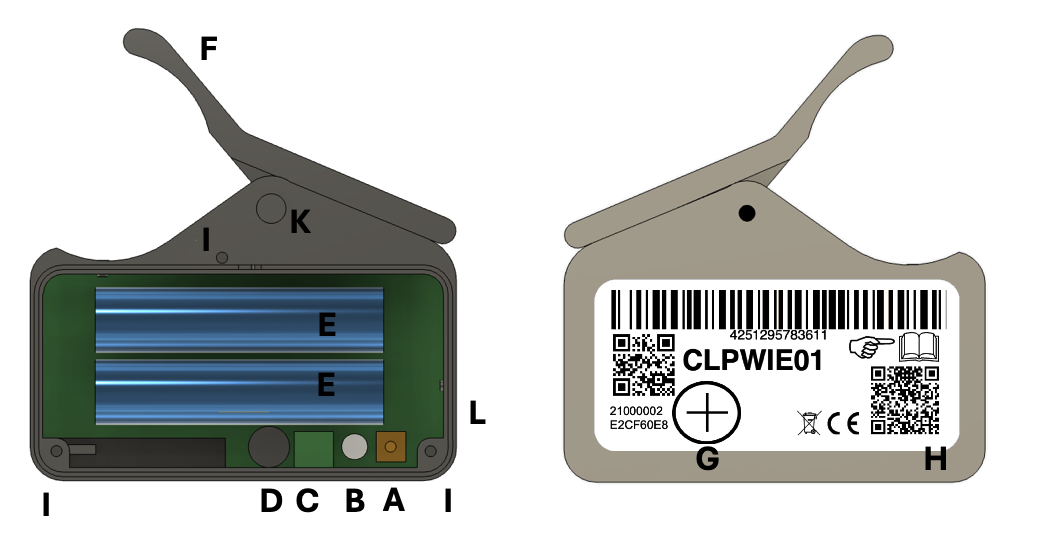
| Buchstabe | Bauteil | Beschreibung |
|---|---|---|
| A | Taster | Zum Anlernen, Testen und Menüzugang (unter dem Batteriefachdeckel) |
| B | LED (zweifarbig) | Zeigt Netzverbindung, Menüstatus und Pairing-Modus |
| C | Schraubterminal | Anschluss für externe 3V-Stromversorgung (+ und − markiert) |
| D | Buzzer | Akustische Signale |
| E | Batteriefach | 2×AAA Batterien |
| F | Bewegliche Klappe | Zur schnellen Befestigung am Wasserrohr |
| G | Transportsicherungsmagnet | Aktiviert/deaktiviert den Sensor |
| H | Rote LED | Alarm-Anzeige und aktive Funkkommunikation |
| I | Schrauben | 3 Schrauben zum Öffnen des Batteriefachs |
| K | Achse der Klappe | Herausziehbar für Kabelbinder-Montage |
| L | Lufttemperatursensor | Misst die Umgebungstemperatur (Richtung Raummitte ausrichten) |
Installation und Inbetriebnahme
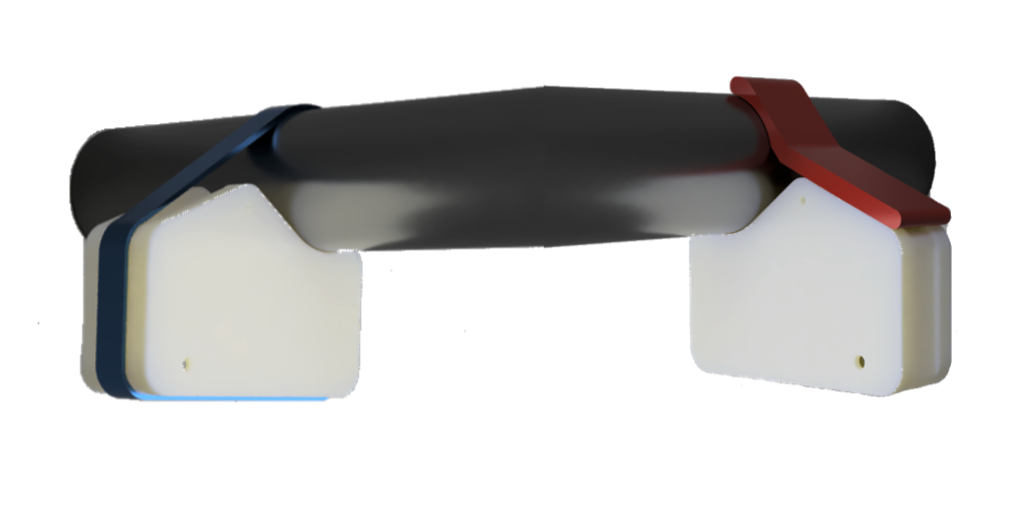
Befestigungsmethode 1: Schnellmontage mit Klappe
Die bewegliche Klappe (F) kann das Gerät direkt am Wasserrohr befestigen. Diese Methode ermöglicht eine schnelle Montage und einfaches Entfernen oder Umsetzen ohne Werkzeug.
Befestigungsmethode 2: Dauerhafte Kabelbinder-Montage
Für eine manipulationssichere, dauerhafte Montage:
- Drei Schrauben (I) am Batteriefachdeckel lösen und Deckel entfernen
- Achse (K) der Klappe herausziehen (mit Hand oder Zange)
- Klappe und Feder entfernen
- Kabelbinder durch die dafür vorgesehene Aussparung im Gehäuse führen
- Sensor am Rohr fixieren
Platzierung
- Montage an der Hauptwasserleitung, ca. 20–40 cm vom Hauswassereingang
- Lufttemperatursensor (L) sollte Richtung Raummitte zeigen (nicht zur Wand)
- Bei unzureichender WLAN-Abdeckung einen Repeater in der Nähe installieren
Bei WLAN-Mesh-Systemen mit mehreren Repeatern kann es etwas dauern, bis sich der Sensor mit dem optimalen Repeater verbindet.
Aktivierung und Deaktivierung
Der runde Transportsicherungsmagnet (G) steuert den Betriebszustand:
- Magnet auf dem Markierungsfeld (großes Plus-Zeichen): Sensor im Schlafmodus, kein Batterieverbrauch
- Magnet entfernen: Sensor wird aktiviert – die rote LED (H) blinkt im Gehäuse (kann bis zu 1 Minute dauern)
- Magnet wieder anbringen: Sensor wird deaktiviert
Verbindung und Kommunikation
Die WLAN-Einrichtung erfolgt über die Konfigurationsseite des Gerätes (SSID „Scope"). Eine ausführliche Schritt-für-Schritt-Anleitung finden Sie unter WLAN-Anbindung.
Dieses Gerät unterstützt auch WPS (kurzer Klick im Auslieferungszustand) und kann per 1-Tasten-Menü (Befehl 5, ggf. gefolgt von Befehl 4 zur Auswahl LoRaWAN) auf LoRaWAN umgeschaltet werden – siehe LoRaWAN-Verbindung.
LoRaWAN und direkte Motorsteuerung per LoRa schließen sich gegenseitig aus. Im LoRaWAN-Modus kann der Sensor keine Aqua-Scope Motoren direkt per Funk ansteuern.
WLAN-Einrichtung (Kurzfassung)
Voraussetzungen:
- WLAN-Netzwerkname (SSID)
- WLAN-Passwort (WPA2-Schlüssel, meist 8+ Zeichen auf der Routerunterseite)
- E-Mail-Adresse für Aqua-Scope Benutzerkonto
Schritte:
- Das Gerät wird im Auslieferungszustand mit rot/grün blinkender LED geliefert
- Mobilgerät oder PC mit dem WLAN „Scope" verbinden (kein Passwort erforderlich)
- Im Browser
http://scope.localöffnen - Formular ausfüllen: WLAN auswählen, WLAN-Passwort und E-Mail-Adresse eingeben
- Weiterleitung zu
https://app.aqua-scope.com - Mit bestehendem Konto anmelden oder neues Aqua-Scope Konto erstellen
- Verbindung am endgültigen Installationsort testen
Installieren Sie den Sensor erst am endgültigen Standort, nachdem Sie eine erfolgreiche WLAN-Verbindung bestätigt haben. Ist dies nicht der Fall, dann ist am Einbauort keine hinreichende Abdeckung mit dem WLAN-Signal vorhanden und Sie müssen einen WLAN-Repeater einbauen.
Für erfahrene Anwender
Neben der Aqua-Scope App stehen weitere Kommunikationsoptionen zur Verfügung, die über Konfiguration → Kommunikationsoptionen in der App aktiviert werden:
- MQTT – Integration in MQTT-basierte Systeme
- Home Assistant – Automatische Erkennung im Dashboard
- JSON Webhook – Eigener Webdienst mit HTTP POST
- Modbus IP – Industrielles Protokoll (TCP Port 502)
- Lokaler Webserver – Direkter Zugriff per Browser im LAN
Der lokale Webserver und Modbus IP sind nur im Netzteilbetrieb verfügbar, nicht im Batteriemodus.
App installieren
- Android: Die Progressive Web App unter
https://app.aqua-scope.comkann als native App installiert werden, wenn der Browser dies anbietet - iOS: Über Safari die Seite öffnen und per Teilen-Menü „Zum Home-Bildschirm" hinzufügen
Grundfunktionen
Regelmäßige Sensordaten
Der Sensor überträgt in regelmäßigen Abständen:
| Messwert | Beschreibung |
|---|---|
| Betriebszeit | Stunden seit Aktivierung |
| Raumtemperatur | Gemessen am Lufttemperatursensor (L) in °C |
| Batteriestatus | Spannung und verbrauchte Kapazität |
| Wasserverbrauch | Geschätzt in Litern |
Alarme
Alarmmeldungen werden sofort bei Erkennung übertragen.
| Alarm | Beschreibung | Verhalten |
|---|---|---|
| Temperatur zu niedrig | Temperatur unterschreitet konfigurierbaren Schwellenwert | Löscht sich automatisch, wenn Temperatur wieder über Schwellenwert steigt |
| Temperatur zu hoch | Temperatur überschreitet konfigurierbaren Schwellenwert | Löscht sich automatisch, wenn Temperatur wieder unter Schwellenwert fällt |
| Leckage / Tropfalarm | Tropfender Wasserhahn oder kleine Leckage erkannt | Löscht sich automatisch, wenn kein Wasserfluss mehr erkannt wird |
| Zu lange Wasserentnahme | Wasser fließt ungewöhnlich lange – mögliche große Leckage | Löscht sich automatisch, wenn Wasserfluss stoppt |
| Batterie leer | Mehr als 80% der Batteriekapazität verbraucht | Batterien wechseln |
Tastenbedienung und LED-Signale
Taster (A) und zweifarbige LED (B) befinden sich unter dem Batteriefachdeckel (3 Schrauben lösen).
Tastenfunktionen
| Zustand | Aktion | Funktion |
|---|---|---|
| Auslieferungszustand (LED blinkt rot/grün) | Kurzer Klick | WPS-Modus umschalten |
| Normalbetrieb | Kurzer Klick | Teststatus per Funk senden (grüne LED bestätigt) |
| Beliebig | >5 Sek. halten | 1-Tasten-Menü aktivieren |
1-Tasten-Menü
Taste länger als 5 Sekunden halten → Menü startet bei Befehl 1 (1× Piep, 1× LED-Blinken).
Bedienung:
- Kurzer Klick: Zum nächsten Befehl weiterschalten (2× Piep = Befehl 2, etc.). Nach dem letzten Befehl beginnt die Zählung wieder bei 1.
- Langer Druck: Vorgewählten Befehl ausführen (3× gelbes Blinken als Bestätigung)
- Timeout: Menü beendet sich nach einigen Sekunden Inaktivität automatisch
Umschaltbare Befehle (3–5) schalten einen Parameter um (Toggle). Die LED-Farbe zeigt den aktuellen Status: rot = inaktiv, grün = aktiv.
| Nr. | Befehl | Beschreibung |
|---|---|---|
| 1 | Linktest | Prüft die Funkverbindungsqualität. Ergebnis: 0 Blinker = keine Verbindung, 1–5 Blinker = Signalstärke (1 = gerade ausreichend, 5 = ausgezeichnet) |
| 2 | Werksreset | Setzt alle Parameter zurück, inkl. WLAN-SSID und -Passwort |
| 3 | Schlafmodus | Ein/Aus umschalten. Im Schlafmodus reduzierter Stromverbrauch; LED und Statusanzeige deaktiviert |
| 4 | LoRaWAN ↔ LoRa Direct | Zwischen LoRaWAN und LoRa Direct umschalten (nur relevant, wenn nicht im WLAN-Modus) |
| 5 | LoRa ↔ WLAN | Wechsel zwischen dem aktuellen LoRa-Modus und WLAN (Standard bei CLPWIE01). Im LoRa-Modus keine direkte Motorsteuerung möglich |
| 6 | Manueller Offset | Manuelle Nachkalibrierung des Vibrationssensors zur Kompensation von Umgebungsänderungen. Nicht anwenden, solange am Rohr Wasser entnommen wird |
Batteriewechsel und externe Stromversorgung
Batteriewechsel
- Drei Schrauben (I) am Batteriefachdeckel lösen
- Deckel entfernen
- Alte AAA-Batterien entnehmen, neue einlegen (Polarität beachten)
- Deckel wieder verschrauben
Es können Standard-AAA-Alkaline- oder Lithium-Batterien verwendet werden.
Externe Stromversorgung
Unter dem Batteriefachdeckel befindet sich ein Schraubterminal (C) mit + und − Markierung für eine externe 3V-Gleichspannung (min. 500 mA, nicht im Lieferumfang).
- Kleine Öffnung (3×5 mm) am Gehäuseboden ausbrechen, um die Kabel durchzuführen
- Kabel am Schraubterminal (C) anschließen (+ und − beachten)
Die Batterien können als Backup im Gerät verbleiben. Durch das Ausbrechen der Kabelöffnung verliert das Gerät jedoch seinen IP44-Schutzgrad – es ist dann nicht mehr gegen Spritzwasser geschützt.
Lieferumfang
- Hauptgerät (Pipe Clip)
- 2×AAA Batterien (bereits eingelegt)
- Betriebsanleitung
- Kabelbinder
Technische Daten
| Parameter | Wert |
|---|---|
| SKU | CLPWIE01 |
| Rohrdurchmesser | 15–32 mm (alle Materialien: Kupfer, Stahl, PEX, PE, etc.) |
| WLAN | 2,4 GHz, 802.11 b/g |
| Bluetooth | Low Energy |
| LoRaWAN | Class A (umschaltbar per Menü) |
| LoRa Direct | Direkte Motorsteuerung |
| Schutzrecht | DE 402025200873-0001 |
Sensoren
| Sensor | Beschreibung |
|---|---|
| 6-Achsen-Gyro | Vibrationserkennung (wenn verbaut) |
| 3× Temperatursensoren | Rohr- und Lufttemperatur |
| Spannungssensor | Batteriespannung |
| Reed-Kontakt | Magnetfeld-Erkennung |
| Rutheniumoxid-Heizelement | Wasserfluss-Erkennung |
Stromversorgung und Batterielebensdauer
| Parameter | Wert |
|---|---|
| Batterien | 2×AAA (Standard-Alkaline oder Lithium) |
| Externe Versorgung | 3V DC, min. 500 mA |
| Ruhestrom | 0,4 mAh/Tag |
| LoRaWAN pro Übertragung | 8 mAs |
| WLAN pro Übertragung | 300 mAs |
| AAA-Batteriekapazität | 1000 mAh (effektiv) |
| Modus | Sendungen/Tag | Lebensdauer |
|---|---|---|
| LoRaWAN | 4 | ~75 Monate |
| WLAN | 4 | ~45 Monate |
| WLAN | 24 | ~12 Monate |
Funkemissionen
| Technologie | Frequenz | Sendeleistung |
|---|---|---|
| WLAN | 2,4 GHz (Breitband nach EN 300 328) | — |
| LoRaWAN | 868–869 MHz | 4 dBm (2,5 mW) |
Abmessungen
| Parameter | Wert |
|---|---|
| Schutzgrad | IP44 |
| Abmessungen | 65 × 20 × 45 mm |
| Gewicht | 57 g (inkl. Batterien) |