KFRMAT01 -- KFR-Motor mit MATTER
Produktbeschreibung
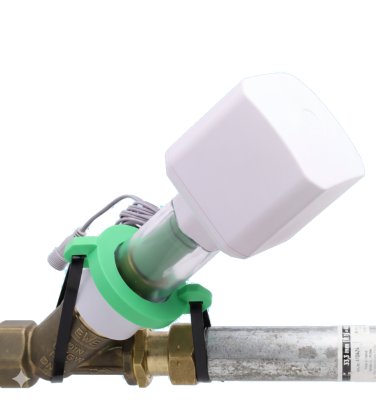
Der Motorantrieb für Schrägsitzventile (KFR-Ventile) ermöglicht die Nachrüstung von bestehenden und bereits installierten Absperrhähnen zu fernsteuerbaren intelligenten Geräten, ohne die Wasserzufuhr zu unterbrechen oder gar in das Wasserrohr zu schneiden.
Der Motor wird über ein 12V-Netzteil versorgt und ist bis zum Netzteil komplett wasser- und schmutzgeschützt (IP67). Optional wird für eine netzunabhängige Versorgung ein Batterieblock angeboten.
Verschiedene Adapterringe und ein ausgeklügeltes Anschlusssystem ermöglichen den Einsatz des Motors an allen modernen Schrägsitzventilen von DN15 bis DN32. Dank eines zusätzlichen Wassersensors, der direkt am Gerät angesteckt wird, kann der Motor zum Leckage-Schutz ohne irgendeine weitere Funkverbindung eingesetzt werden.
Steuerung: Über MATTER-Protokoll -- steuerbar über Apple HomeKit, Google Home, Amazon Alexa, Samsung SmartThings und Home Assistant.
Bauteile des Motorantriebes
| Kürzel | Bauteil | Abbildung |
|---|---|---|
| H | Handrad | 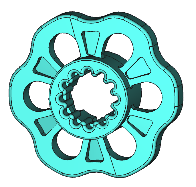 |
| K | Innerer Koppler | 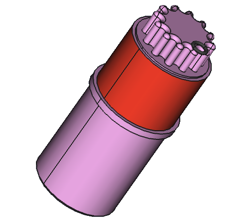 |
| Ax | Adapterringe (A1--A4) | 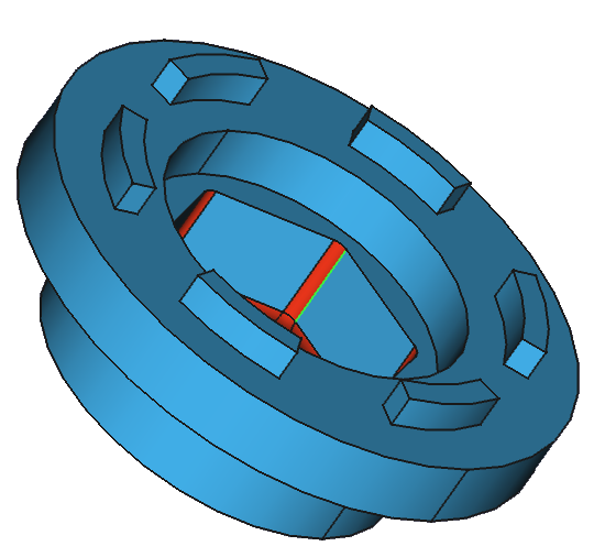 |
| D1, D2 | Distanzringe (12 mm, 24 mm) | 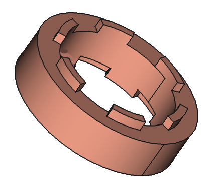 |
| Ws | Kugellagersitz | 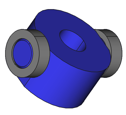 |
| M | Motor mit Taste | 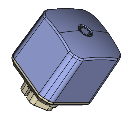 |
| G | Gehäuse | 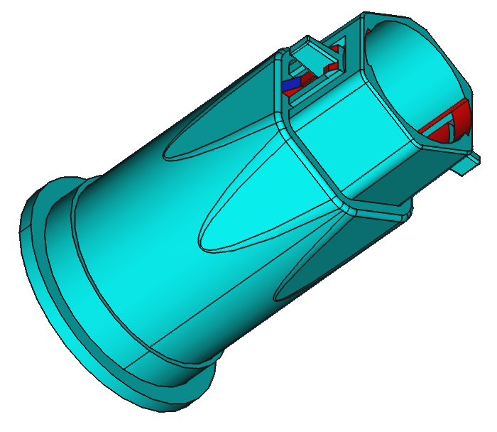 |
| N | Niederhalter | 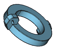 |
Montage des Motorantriebes
Anbau an das Absperrventil
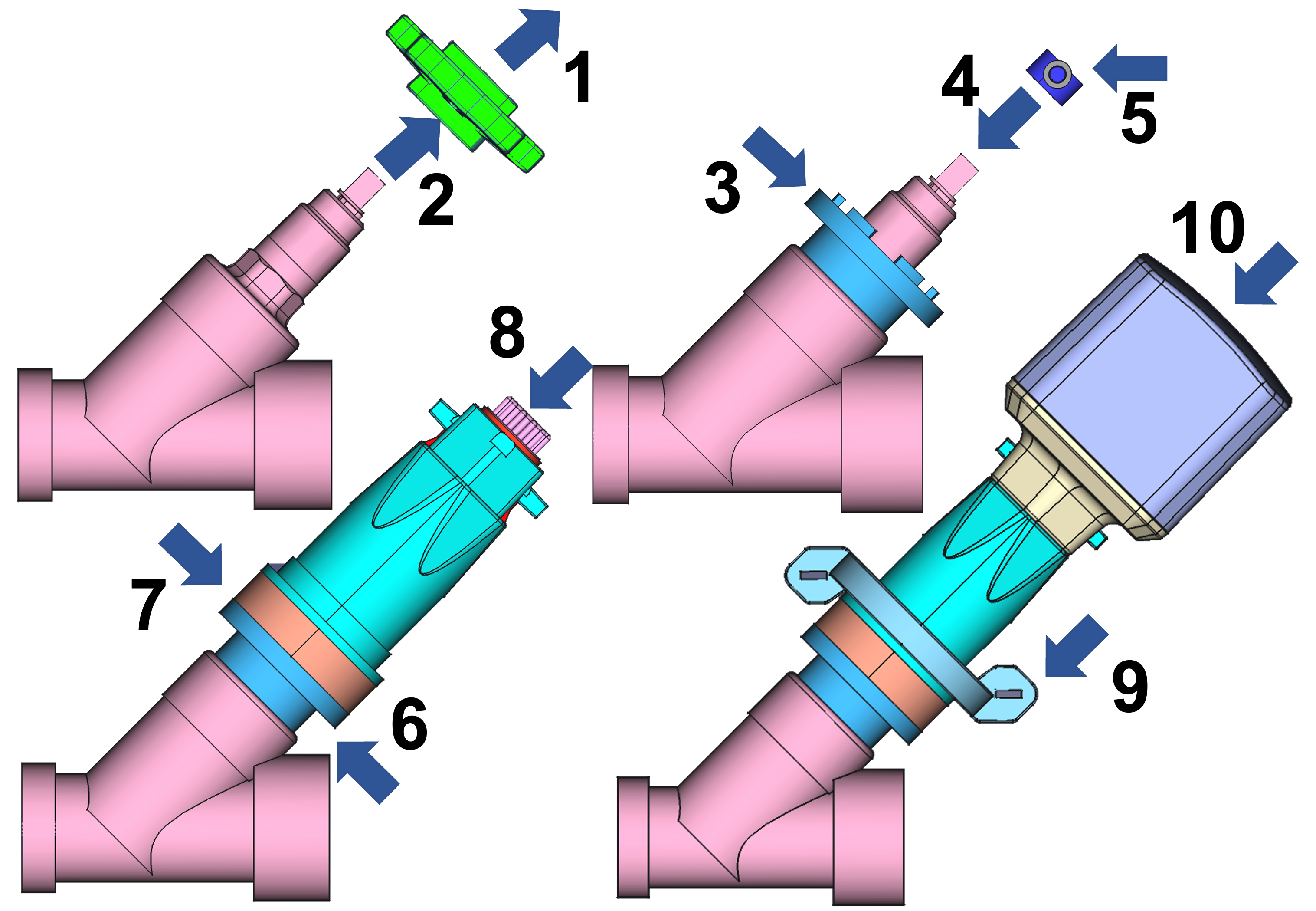
- Schraube im Zentrum des Handrades lösen
- Handrad entfernen
- Adapter A1--A4 wählen (M17, M22, M27, M30)
- Kugellagersitz W1--W3 auf Spindel setzen (6x6, 7x7, 8x8 mm)
- Kugellagersitz mit Schraube fixieren
- Distanzringe D1/D2 bei Bedarf (12 oder 24 mm, kombinierbar zu 26 mm)
- Gehäuse aufsetzen
- Inneren Koppler einsetzen (durchsichtiges Gehäuse zur Kontrolle)
- Niederhalter mit Kabelbindern um das Rohr befestigen
- Motorkopf auf Gehäuse setzen
Beim Aufsetzen des Motorkopfes darauf achten, dass die Zahnräder korrekt ineinandergreifen. Bei Widerstand den Motor leicht drehen.
Ventile von Wilhelm Ewe GmbH
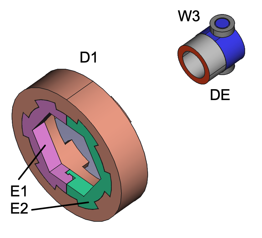
Geteilter Ring (E1+E2) in 24-mm-Distanzring einsetzen statt Adapter. Kleiner Distanzring (DE) unter Kugellagersitz für Fettkammer.
Eigener Adapter
Wenn kein passender Adapter für den Ventilsitz vorhanden ist, muss einer passend gemacht werden. Dazu wird ein Adapter ausgewählt, der über den Ventilsitz passt, und der Zwischenraum mit einem Zweikomponenten-Harz ausgefüllt (liegt dem Motor bei):
- Ein Stück der Masse mit einem Cuttermesser abschneiden
- So lange kneten, bis eine einheitliche Farbe entsteht
- Lücken zwischen Adapterring und Ventilfuß ausfüllen
- Nach Aushärten des Harzes den nun passgenauen Adapterring verwenden
Das Harz wird fest am Ventil haften. Ist dies nicht gewünscht, hilft es, das Ventil leicht mit Öl zu bestreichen. Dann lässt sich der ausgehärtete Adapterring leicht entfernen.
Gleicherweise kann ein Kugellagersitz für eine Ventilachse mit kleiner als 6x6 mm Vierkant angepasst werden. Bitte darauf achten, dass die Spindel genau konzentrisch im Kugellagersitz eingepasst wird.
Einstellen der Endpositionen
Nachdem der Motor montiert und mit Strom versorgt ist, muss er die korrekten Endpositionen für AUF und ZU ermitteln:
- Ventil manuell in die AUF-Position drehen, bevor der Motor erstmalig aufgesetzt wird. Die optimale AUF-Position ist ca. 2 Umdrehungen in Richtung ZU nach Erreichen des Anschlages in Richtung AUF (entgegen Uhrzeigersinn).
- Motor mit Strom versorgen.
- Taste einmal kurz drücken. Der Motor fährt kurz in beide Richtungen und erkennt, ob er in der AUF- oder ZU-Position ist. Die LED-Farbe zeigt die erkannte Position an.
- Beim ersten ZU-Befehl (per Tastendruck oder Steuerkommando) fährt der Motor bis zum Anschlag in die ZU-Position und dreht danach ganz leicht zurück -- diese Dichtungsentlastung schont die Gummidichtung im Ventil.
Der Motor muss beim ersten Einschalten in der AUF-Position stehen, damit die automatische Kalibrierung korrekt funktioniert.
Dichtungsentlastung ein-/ausschalten:
Sollte die Gummidichtung durch langes Geschlossen-Halten oder Alterung spröde geworden sein, kann das leichte Zurückdrehen zu einer Undichtheit führen. Die Funktion kann daher deaktiviert werden:
- Per App: Im Bereich „Konfiguration" (bei Kopplung mit internetfähigem Sensor)
- Per Taste: 6 Sekunden gedrückt halten (6x Buzzer), dann loslassen
- 2x Beep + 2x grüne LED = aktiv (Werkseinstellung)
- 3x Beep + 3x grüne LED = deaktiviert
Sobald die Endlagen erkannt sind, fährt der Motor nicht mehr hart gegen die Endpunkte, sondern zählt die Umdrehungen und fährt die Endpunkte sanft an.
Externer Kabel-Wassersensor
An das Gerät kann optional ein kabelgebundener Flutsensor angeschlossen werden. Es gibt einen Stecker am Netzkabel beim Motor. Entfernen Sie den blauen Gummistopfen und stecken Sie den Sensor ein. Bitte drücken Sie den Stecker mit etwas Kraft, um eine wasserdichte Verbindung zu gewährleisten.
Wenn der Sensorkopf Wasser feststellt:
- Akustisches Signal ertönt
- Ventil schließt sich automatisch
- Rote LED blinkt (Alarm)
- Alarmmeldung wird per Funk abgesetzt
Sobald der Sensorkopf frei von Wasser ist, kann der Alarm gelöscht werden:
- Taste 2 Sekunden lang drücken, oder
- Per Funk (App oder Steuersignal)
Der Flutsensor kann mit einer 1,5-m-Verlängerung ALIEXT01 (im Shop erhältlich) verlängert werden.
Bedienung am Gerät
Das Gerät hat eine einzige Taste mit einer eingebauten dreifarbigen LED. Zum Schalten des Ventils können Sie auf die Taste klicken oder die Taste einige Sekunden lang gedrückt halten. Der Motor piept jede Sekunde als Zählhilfe.
Das Gerät ist für den Außeneinsatz konzipiert und verhindert Fehlfunktionen durch Wassertropfen auf dem Knopf. Drücken Sie die berührungslose Taste daher bitte fest, auch bei kurzem Klick.
Tastenbedienung
| Aktion | Funktion |
|---|---|
| 1x Klick | Motor schalten (Auf ↔ Zu) |
| 2 Sek. halten | Alarm deaktivieren |
| 2x Klick | Statusreport aussenden |
| 3 Sek. + 1 Klick | Tastenschutz aktivieren |
| 3 Sek. + 3 Klicks | Tastenschutz deaktivieren |
| 4 Sek. + 1 Klick | Motor bleibt geschlossen nach Sensor-Alarm (Werkseinstellung) |
| 4 Sek. + 2 Klicks | Motor öffnet sofort wieder nach Sensor-Alarm |
| 6x Klick | Dichtungsentlastung ein/aus (2xBeep+grün = aktiv, 3xBeep+grün = deaktiviert) |
| 10 Sek. + 5 Klicks | Motor komplett zurücksetzen (3xBeep + 3x rote LED = OK). Nur nötig bei Moduswechsel (LoRaWAN ↔ Direct ↔ Sensor-Kopplung) |
LED-Signale
| LED | Bedeutung |
|---|---|
| Grün langsam blinkend | Ventil offen |
| Rot langsam blinkend | Ventil geschlossen |
| Rot+Grün schnell blinkend | Motor bewegt sich |
| Rot blinkend | Alarm |
| Rot dreifach blinkend | Motor ist blockiert |
| Gelb blinkend | Sucht Verbindung zum Funk-Netz |
Verbindung mit einer MATTER-Steuerung
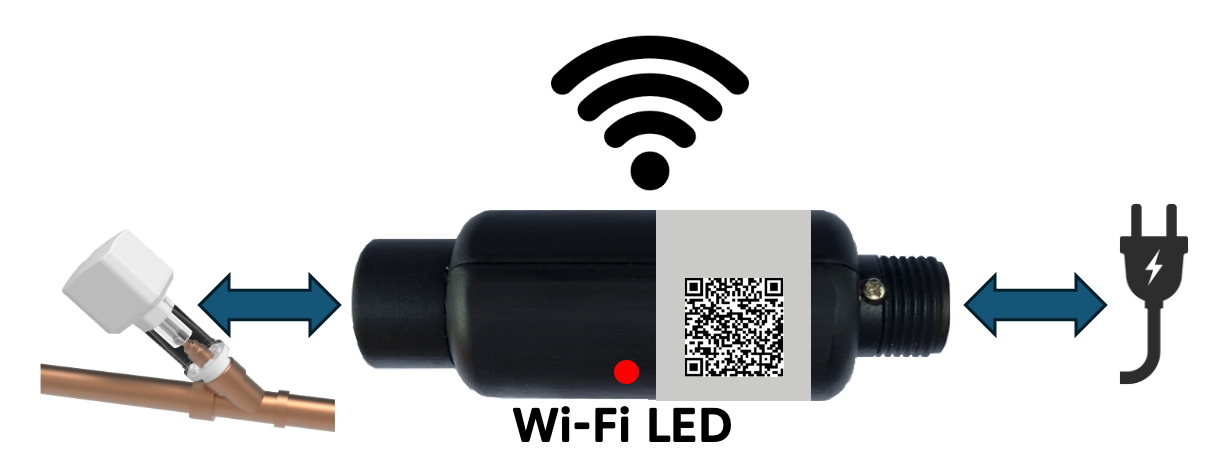
Die Matter-Funkverbindung erfolgt durch das Matter-Modul, das zwischen die Kupplung der Stromversorgung des Motors geschraubt wird.
- QR-Code auf dem Matter-Modul scannen
- LED blinkt alle 4 Sek. -- Pairing-Modus
- LED blinkt jede Sek. -- Pairing gestartet
- Werksreset: Taste 5 Sek. halten
Lieferumfang
- Motor mit Stromkabel (150 cm)
- 4x Adapterringe (M17, M22, M27, M30)
- 3x Kugellagersitze (6, 7, 8 mm)
- Distanzring + Spaltring für Ewe-Ventile
- Halterung + 2 Kabelbinder
- Hauptgehäuse + interner Koppler
- 2x Distanzringe (12 mm, 24 mm)
- Externer Flutsensor
- Netzteil (150 cm)
- Ersatz-Handrad
- 57 g Epoxidharz
- Benutzerhandbuch
Technische Daten
Motorantrieb
| Parameter | Wert |
|---|---|
| SKU | KFRMAT01 |
| Drehzahl | 15 rpm, max. 40 s Auf/Zu |
| Leistung | 10,95 W |
| Getriebe | 1:704, max. 4,5 Nm |
| Geräusch | <50 dB |
| Adapter | M17, M22, M27, M30 |
| Ventilspindel | 58--135 mm |
| Rohrdurchmesser | DN15--DN32 |
| Gewicht | 380--420 g |
| Abmessungen | 70 x 170--195 mm |
| Motor | ~400 mA, Standby ~50 mA (12V) |
| Schutzgrad | IP67 (Netzteil IP20) |
| Betrieb | -20 bis +60 °C |
| Lagerung | -30 bis +70 °C |
| Mindestabstand Wand | 35 mm |
| Vertikaler Platzbedarf | 175 mm über Rohrdurchmesser |
| Vibration | <10 dB |
Funkkommunikation
| Parameter | Wert |
|---|---|
| WLAN | IEEE 802.11 b/g/n 2,4 GHz |
| Protokoll | MATTER |
| Kompatibel | Apple, Google, Amazon, Samsung, IKEA, WAGO, Home Assistant |